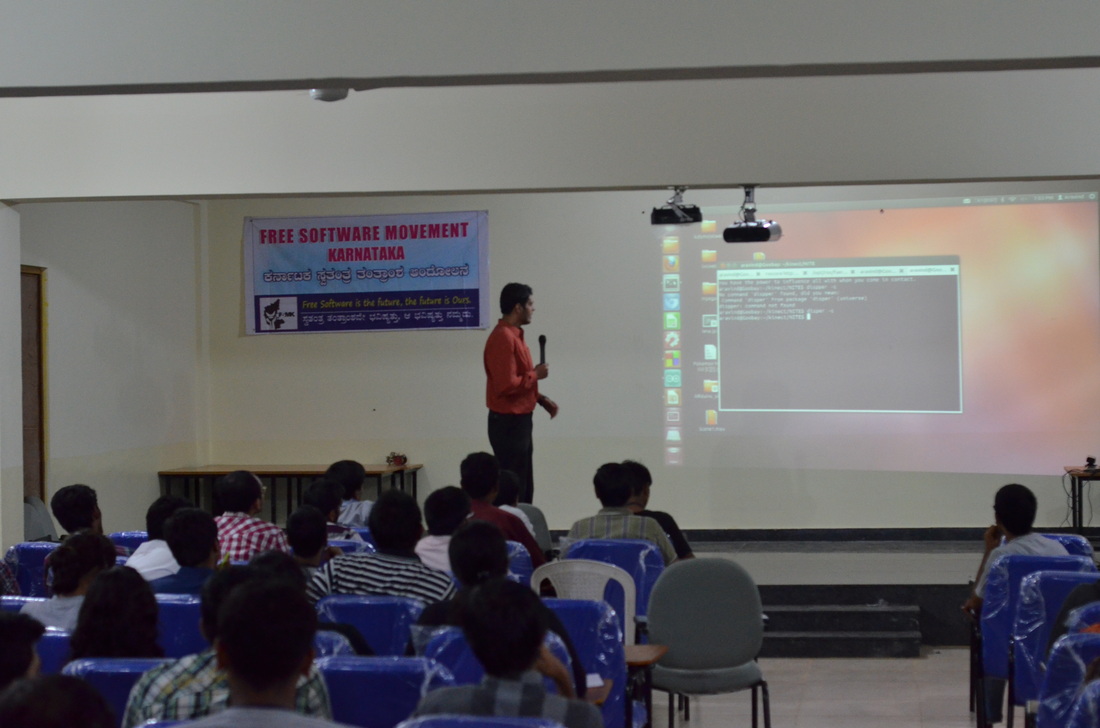
FSMK conducted a 5 day residential workshop at svit during the last days of January. We were invited to give a talk on product development using free hardware.
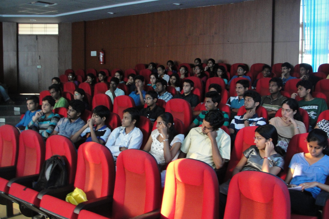
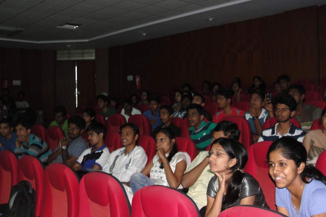
The talk was attended by around 150 students from various colleges spread across karnataka and some from outside karnataka too.
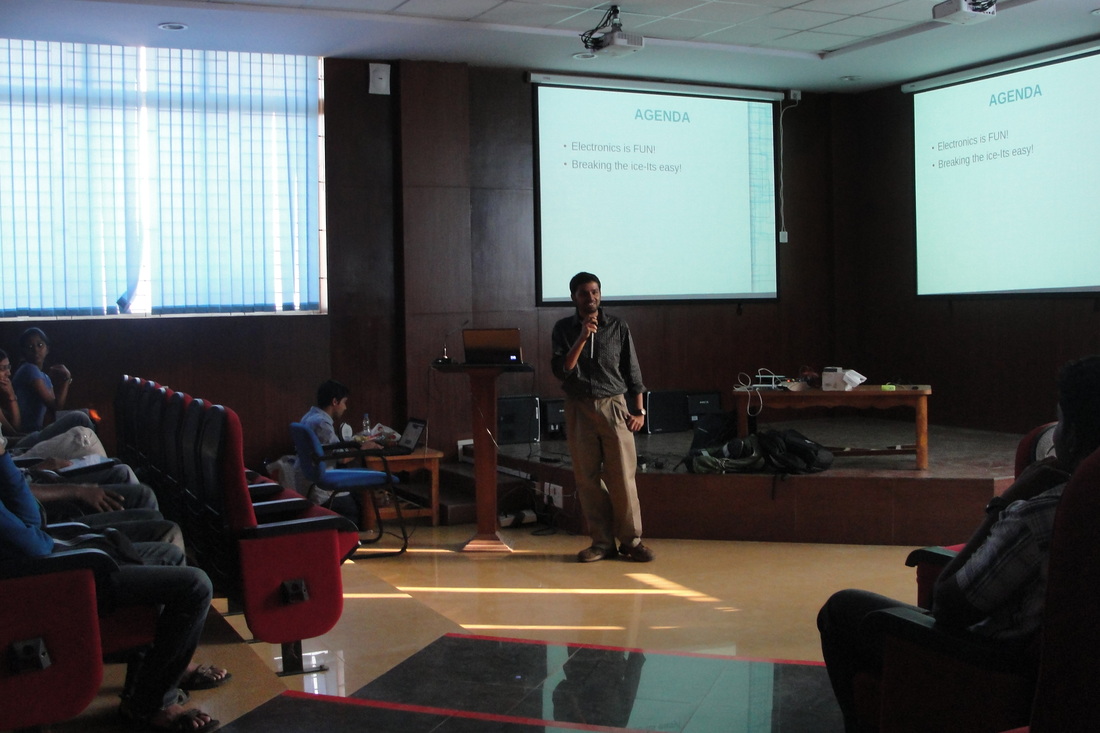
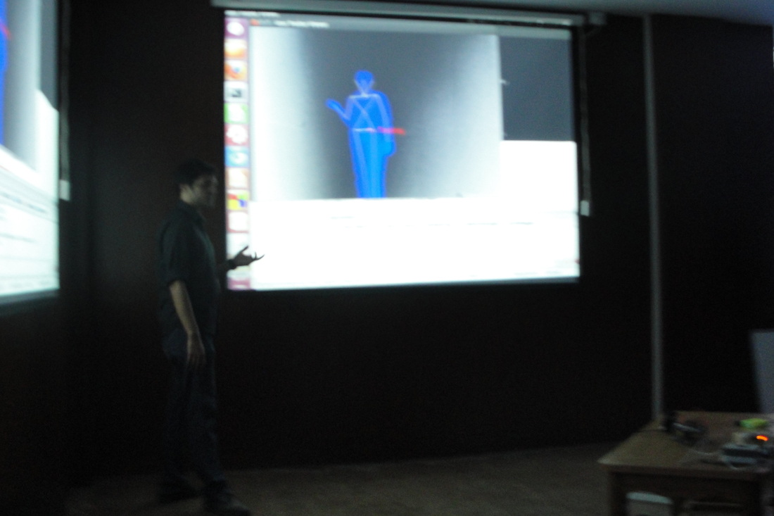
Aravind Started the talk by explaining how a basic hobby idea can be made and then grown into a complete product for development. Explaining this with the evolution of the basic obstacle avoider bot to a remote controlled one to a gesture based bot.
The audience seemed to be enthralled by the demo’s given, and hopefully they have been inspired to work on their own and contribute to the community.
I guess by now most of us, coding freaks by now are into arduino directly or indirectly. One major problem we all have faced with arduino is the frequent deletion of the boot-loader from the Atmega IC. There could be N number of reasons for this, and I shall not get into that. I will give you a way to solve this problem and also convert your normal atmega chip to an arduino chip.(Most of you pro's will tell me AVR and Arduino are the same. YES they are, but for those freshers who have just been introduced to AVR and Arduino take them as different things, as time goes you will know what I mean)Requirements to boot-load:
1) A programmer or another working arduino board.
2)the board you want to boot-load.
3)6-7 plugs(wires)
Procedure:
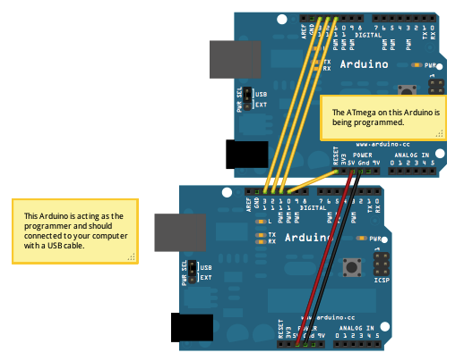
step1: connect your programmer to the arduino IC. the pins are as follows:
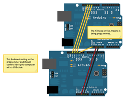
pin 13,12,11 on the arduino corresponds on sck,miso,mosi respectively. use this config to connect to the usbasp.
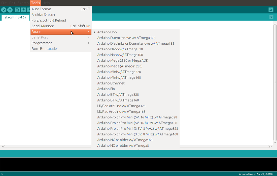
step 2: on the arduino IDE(arduino1.0 and up) select the corresponding board which you want to boot-load
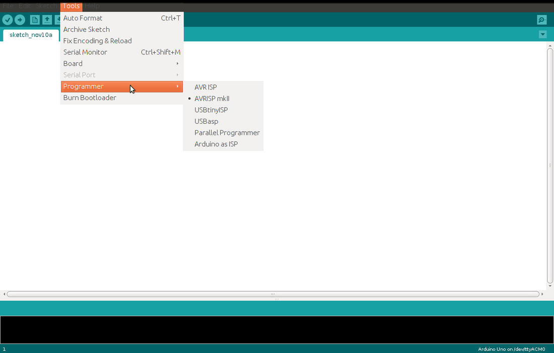
step 3: select your programmer.(usbASP or if your using arduino itself select arduino as ISP)
step 4: connect the programmer to the computer.
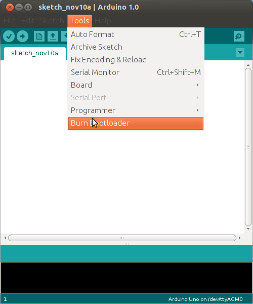
step 5: in the arduino IDE select tools>burn bootloader
step 6: plug out the arduino and now get coding on your freshly bootloaded chip!!!
SJCE Mysore conducted their yearly tech event,tuxedo this weekend. A completely opensource event where students and industry people present talks and small workshops based on FOSS.
It was quite interesting to see a collage so much into FoSS,unlike the collages i've seen in Bangalore There was a prof who gave a talk on latex a software for making tech papers. He was using zen walk OS. He also kept inspiring his students to work on linux. To add to that he has contributed few clip arts for paper presentations. Parallelly the linux computing group of SJCE had their event, various coding competitions and talks.
The college has its own hardware and software groups which conduct workshops and also attend various other events.
Our talk was an introduction to freedom hardware ,though many of them were acquainted with various technologies ,the idea of community learning was something new to them.
The session was attended by about 50 students from circuit branches and spread across all semesters . They loved the various demos on kinect and pi. A large group showed interest and came back for offline discussions.
Being optimistic and patiently waiting to see the results of the talk :-)
The NSK arduino boards were not working on ubuntu as expected.
The fix for this is quite simple,
Connect the reset pin to 3.3V or 5V and then program the arduino. It should work. Im still not sure if this was an error with the FTDI hardware, or if its the software causeing the issue. Im guessing its the ftdi driver on linux which is negating the DTR line. If someone can fix that it would be great.
But as of now, those of you who had the NSK boards can now use it on ubuntu with no issue. Just connect the 5V or 3.3V to the reset pin.
The toughest part of getting your self to work is the first project. Once you've over come this first project the rest seem much more easier. This post basically aims at getting one started. A few steps i think will help you get past this learning curve with a little ease.
Step 1: Define the problem statement clearly for yourself, Write down all the requirements, dont go too technical. Just mention on the outside what you want your project to do.
Step 2: Break up step one into different parts. Go technical here. Break it into, mechanical, coding, Hardware electronics. and then further down into different components.
Step 3: Start writing down your plan for each component. If its a program write the algorithm and logic for it.
For, Electronic circuits a block diagram, mechanical part put down the designs.(Dont be too technical here again)
Step 4: List down all the components you need for your project. In case there are things your not cirtain of get a way to conduct some tests on it. that is: instead of buying all the components get one of it and see if it works the way you want it to.
Step 5: Get all the components and dependencies required by your project.
Step 6: Convert the Flowcharts and designs into actual code and the block diagrams into complete circuits.
Step 7: Test the components you've made separately.
Step 8: Put them all together. you’ll have your idea materialized.
Step 9: Test the complete product.
Step 10: Feel happy and start a new project.
This is just a birds eye view of how you should go about your project.
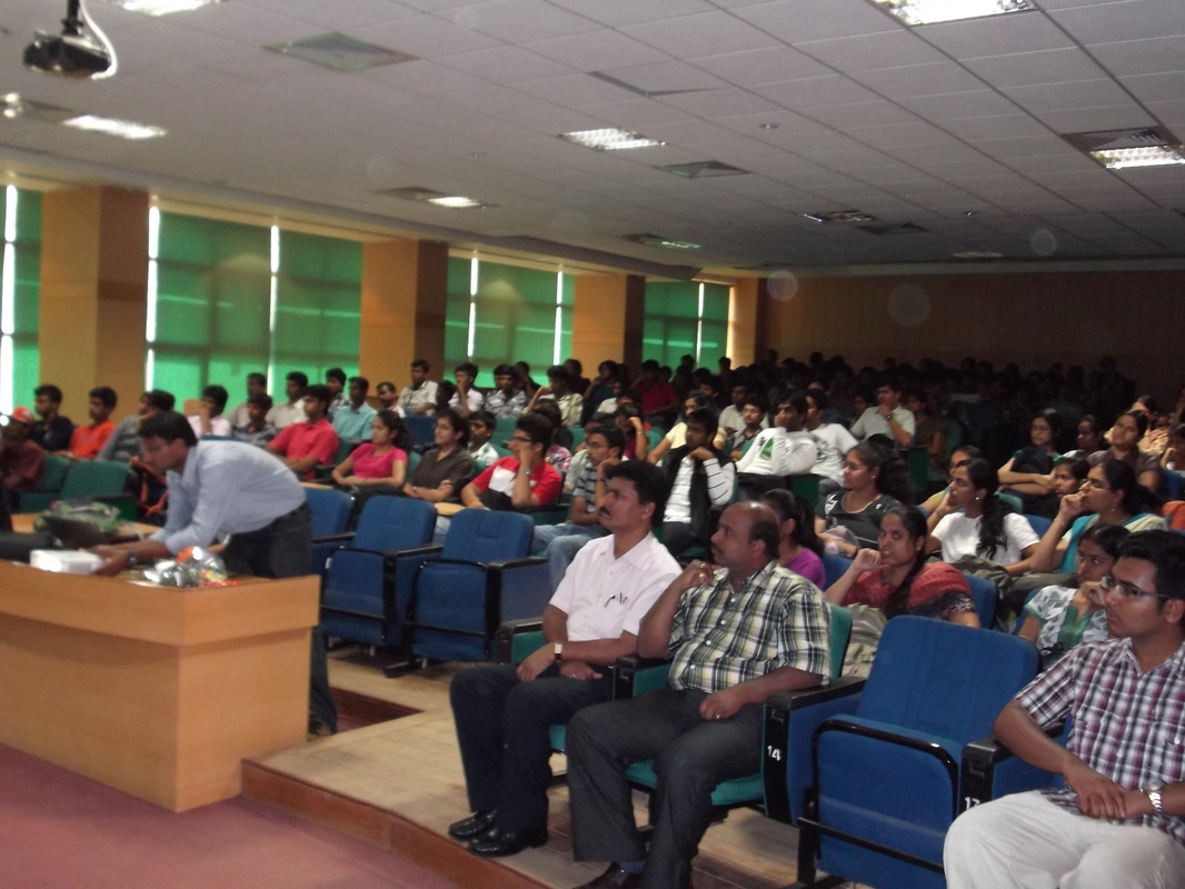
The day started off with talks, Surprisingly we had a jam packed auditorium.
Talk 1: Jaykumar and Senthil from FSMK(Free Software Movement karnataka) gave a brief talk on the on-going free software movement and the need for a parallel hardware movement.
Talk 2: Me (Ashfaq) presented the idea of Freedom hardware and its need in our world.
Talk 3: Prof. Dinesh from IISc spoke about product development, Inspiring students to start working of various projects.
Talk 4: Aravind(Junior Research Fellow @ IISc gave a demo of interfacing the arduino and Raspberry and controlling a motor over the internet.
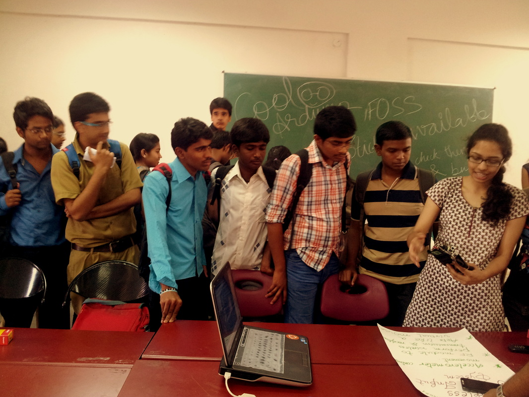
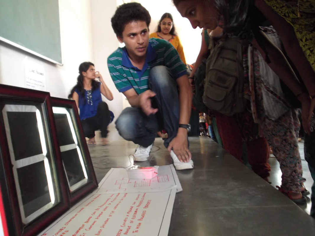
This was then followed by an open house exhibition.Students displayed projects done by them.
The Projects on display:
Hardware based.
1. Line-follower.-Basic line follower made using a motor driver and Ir sensors
2. Manual bot- Manually controlled wireless bot.
3. Wi-Gi(wireless Gesture Input ) - A glove which controls the mouse on your computer,taking the movements on the Hand.(using wireless communication)
4.Kinect:- A bot the follows you!!
5. 7-segment Display-A basic 1ft by 1ft display made as a display for basket ball matches,done by students.
6. Speaker-A simple arduino Project which takes input from a tv remote(via IR, and plays a tone)
7. PIR.-The door was hooked with a pir sensor, which would count the number of people entering the hall.
8. Power Supply- the basic bridge power supply, used to explain basic capacitance to students.
9. Led Cube: using arduino( 4X4X4 cube)
10:EMF sensor: an arduino based project that would give display the reading of radiation present in the air.
And many more projects....
Software Projects:
1. Web programming: Basic Html website.
2. Fun with Bash:explaining the bash script.
3. Blender:animation using blender.
4. Kernel compilation
5. Rahul's Table: Rahul our web developer explained various upcoming technologies in website building.
6.Filters on octave
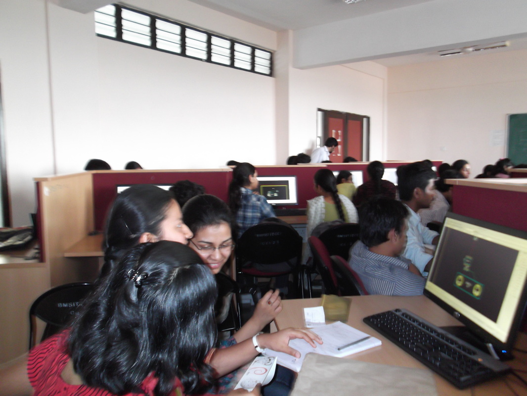
In parallel to the exhibition a workshop on PCB designing was conducted. The workshop taught the student s to use Kicad for designing PCB and also a brief explanation on how to fabricate them at home.
We had planned to cater to 30 students, but surprisingly we had a demand for more than 150 registrations. hence the workshop was conducted in 3 sessions of about 45-50 students each.
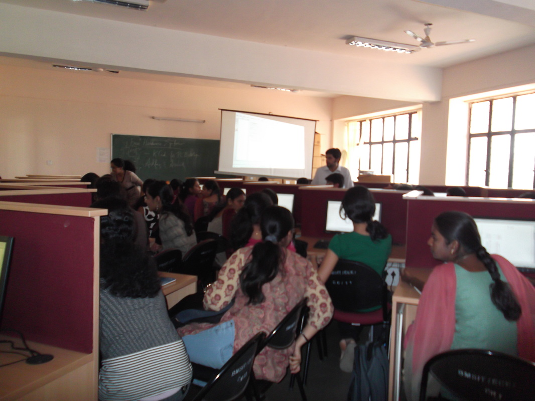
Audience
The Road Ahead!
This event got many of the students interested in the movement, now we plan to help them work on projects by providing technical support and also giving a common platform to learn,share and teach.
The internet has grown to connect a very large user base in recent times, but still bandwidth remains limited. Images take up a large amount of bandwidth. Hence we make use of different image compression methods. One famous format is the JPEG(joint photographic Experts Group).This format makes use of Discrete cosine transforms. In this post we will try to understand the simple idea behind DCT(Discrete Cosine Transformations).
For our demo I will be using Octave(it is an equivalent of Matlab).
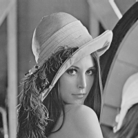
I will be using the following image, which is a 512x512 image. As shown:
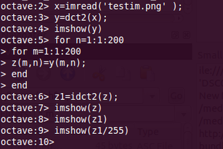
The code for understanding DCT is fairly simple.
- The first line reads the image into the matrix 'x'. By this, the image can now be imagined as a matrix of 512 rows and 512 columns and each value of the matrix corresponds to the contrast of that part in the figure.for example the eyes in the image may correspond to the location of [260,256]. Therefore the matrix value at this address is 0 indicating completely black. (on a scale of 255, where 255 is white). If the picture was a colour image, the matrix would be of the size 512X3,512X3 where the first three values refer to the RGB of the first pixel(Red Blue and Green values. This is referred to as a 3 channel image).
- Next we find the DCT of this image and store it on 'y'.Remember that the DCT is not really a one to one mapping like the case above (each matrix entry is not really referring to the complete information of the picture).Instead the entries refer to the weights of the pixels. Not going much into the thoery, lets move on.
- The next 5 lines of code is used to take a part of the matrix 'y' and save it onto matrix z. Here only 200x200 elements of the matrix 'y' are saved on 'z'.The plot of 'y' and 'z' are show later.
- The above operation is similar to cropping of the image.
- Now we find the inverse DCT of the matrix 'z' this should give us the image back, but it will not. a scaling factor of around 255 is required,either multiply or divide play around to find the correct one.Divide works for me.
- Hence the line: imshow(z1/255).
The resulting image is shown along side. Now to understand what we actually did we have to look at the details of the image.
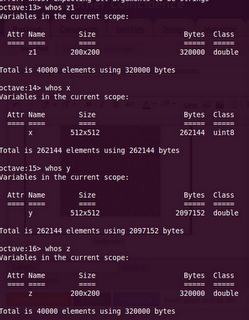
Just type in "whos z1" (without quotes)in your main terminal and u will see that the resulting image is a 200x200. Not only has the image been re-sized but the important point is we recovered the complete image with only 200x200 values of the DCT. This is what we mean by energy compaction,where the most of the image data is stored in the first few elements of the matrix. So instead of having a 512x512 information where each pixel data is important to define the picture, we have converted that to a set of 200x200 matrix where the first few entries talk about the contrast of the whole picture and the rest are data which can be 'mutiplied' in a sense of saying to the contrast to get the whole picture.
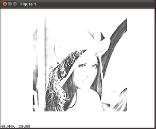
The output image
|

Image details
|
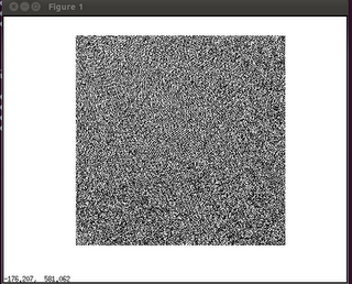
imshow for the DCT image.
Hope this post has made you understand and appreciate image processing and mainly maths. Comments are welcome! :)


 RSS Feed