Button Interface
Right! so we got an LED blinking on a pin. Cute,but not effective if there is no control over it. Here's the next part then, to interface a button to the Arduino, to blink the led manually.
Again, the code is very simple. The circuit is also simple, but we're going to touch upon theory a little more to make it more effective and learn electronics at the same time.
So let's get started! Onto the Theory!
Again, the code is very simple. The circuit is also simple, but we're going to touch upon theory a little more to make it more effective and learn electronics at the same time.
So let's get started! Onto the Theory!
Theory

The classic push button is what we'll learn to interface in this segment. A button is just like a retractable short between two pins. So when you press the button all you are doing is connecting two pins and forming a path for the current to flow between them and if the arduino detects the current it assumes an input has occured. The direction of the current acts as the 'edge detection' . We'll come to this later.
Again, the only parameters we worry about is the voltage and the current. In this case the voltage doesn't play a role cause the button works at any voltage(its just forming a path!). Its current dependent in the sense that u can probably give around 2A before the button pin melts :D. Anyways,the Arduino input pin is voltage dependent. Hence we'll design a voltage based approach as follows.
If we were to put a button between the Arduino and GND , one pin to each, then when we press the button, its equivalent to that pin being directly connected to GND(current flowing towards GND) and when the button is not pressed, its as if the Arduino pin was open(not connected to anything and hence no current flow). This should work great if your code were to be like
If(PIN==GND) {do}
else{ do somethine else}
But, this is not a good way to code because when the pin is open, its like a small antenna which can take in noise and this noise might give erroneous readings. Its best to keep the pin either at high or low. So, the best way would be to do the following
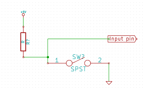
Analyzing this yet again simple circuit, we can notice that the input pin is default powered by the 5V supply through the resistor as long as the button is not pressed(the ends are not shorted to GND). Once the button is pressed, the Input pin is brought to 0V, giving the effect of a 'falling edge'. This can be recognised as a button press.
Hence we can now write a better code..one when the input pin reads a HIGH and one when it reads a LOW.
Now we are ready to move on to the practical section!
Hence we can now write a better code..one when the input pin reads a HIGH and one when it reads a LOW.
Now we are ready to move on to the practical section!
Practicals:
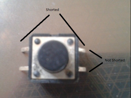
Physical description of most push buttons are as shown. The leads which are NOT nearer are shorted, which means they are the same pin, and the ones nearer are not shorted, which will be the pins that we shall use.
Components Required:
- Arduino Uno
- Push Button
- 10k and 330 resistor
- Red LED
In this example we shall interface a button to the Arduino to toggle an LED.
Components Required:
- Arduino Uno
- Push Button
- 10k and 330 resistor
- Red LED
In this example we shall interface a button to the Arduino to toggle an LED.
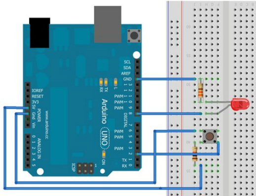
Yes, the circuit is a little poor in design but the idea and implementation are very simple!. Using the same idea as above in the circuit, we have interfaced the button to Digital Pin 2 of the Arduino keeping the LED at pin 8.
This way the press of a button should be read at pin 2 and effected at pin 8.
We will do two small examples related to push buttons.
The first piece of code we will write is very simple. when the button is pressed, the LED will glow and when it is let go the led goes off.
The code for this is as shown below.Go ahead open up the button code from examples->digital->button
The CODE
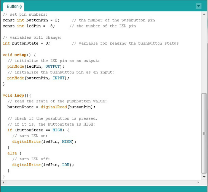
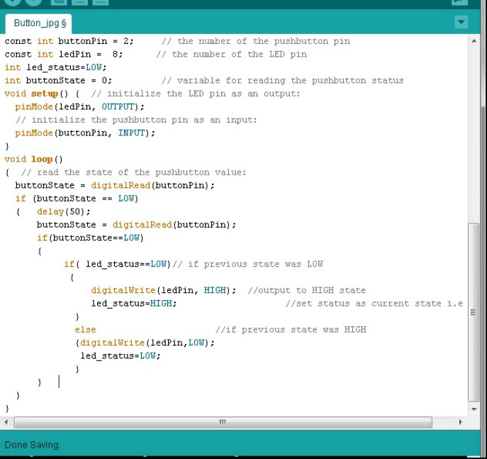
Once the code is loaded remember to change the ledPin value to 8 as thats where our led is!
Again here we have the two functions, the setup which is straightforward. It initializes pin 2 as INPUT and pin 8 as OUTPUT. Notice the use of global variables ledPin and buttonPin. These are just to avoid confusion. You can always put the number directly.
In the loop function we see what is called 'polling'. This refers to reading the input pin at frequent duration and based on the reading, an if else statement effects the output led. The digitalRead function returns the status of the input pin(HIGH if button unpressed or LOW if button is pressed).
Straightforward right?
Now the problem here is quite obvious. The LED glows only when the switch is held down. Once its let off, the LED turns off too. So, how are we going to fix this?
It might instantly strike that instead of turning the LED on when the switch is pressed, we just toggle the LED that is
int led_status = LOW;
if (buttonState == LOW)
{
if( status==LOW)// if previous state was LOW
{
digitalWrite(ledPin, HIGH); //output to HIGH state
led_status=HIGH; //set status as current state i.e HIGH
}
else //if previous state was HIGH
{
digitalWrite(ledPin,LOW);
led_status=LOW;
}
}
This would remember the previous state and toggle the led. This should theoretically work. But when you test this u'll see a problem. The LED say 3/10 tries might not toggle. This is cause of the 'switch debouncing' effect.
This brings us to the second piece of code.. The actual button interface to arduino.
Code 2
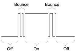
When a switch is pressed, there is a change from one state to another(HIGH to LOW or vice versa). Because of the imperfections of the switch, the first contact need not be firm, that is to say when we press the switch, the pin takes time to settle down to the GND value, because the switch toggles from contact to no contact a couple of times before establishing a firm contact between its leads as shown beside in the picture.
This can be wrongly read by the Arduino as a series of press and release of the button, which makes the led blink a couple of times before settling to the appropriate value.
To overcome this we give a delay function so that once we read the pin status we check again after a small delay in the order of milliseconds to see if the change actually occurred or if it was due to debouncing effect.
Slightly modifying the above program we get,
if (buttonState == LOW)
{
delay(50); buttonState = digitalRead(buttonPin);
if(buttonState==LOW)
{
if( status==LOW)// if previous state was LOW
{
digitalWrite(ledPin, HIGH); //output to HIGH state
led_status=HIGH; //set status as current state i.e HIGH
}
else //if previous state was HIGH
{
digitalWrite(ledPin,LOW);
led_status=LOW;
}
}
}
So what we are doing here is to first see if the button was pressed(i.e shorted to GND). If so, wait for 50mS and again check if it really went LOW. If it did then toggle the LED. else do nothing. This is the perfect way to interface a switch to the Arduino. The final code is as shown below.
And there you go! That completes the second tutorial for Arduino. Hope it was easy enough :)
Food for Thought
Here are some Questions:
Q.Why the resistor? why not just directly one pin to 5V and the other to GND?
A. Well!, when you press the switch you will be shorting the 5V directly to GND right? that would damage your power supply. The resistor exists for the sole purpose of limiting the current when the switch is pressed between the power and GND.
Q.Does it mean i can use any value of resistance as long as the power supply can handle the current?
A. Yes you can in theory! but practically a small part of the current will also flow into the Arduino.We do not want that part though a small fraction of the major to affect the Arduino when the switch is not pressed.Also why waste current? keep a low current flowing in the circuit at all times to efficiently use power. But not so low that the Arduino wont even detect it!.
Q.Is debouncing really an issue? it will eventually settle to one state before we realize..
A. It matters when you are using the button to count an event. You wouldn't want it to count many times when its only once. :P
Q.I'm an EC student, we have studied in our curriculum that the pins have an internal pullup resistor to 5V so that we need not use the external resistor.
A. Yes dude, you are right! but theory and practicals are different :D . It is a weak internal pullup to 5V. There are always chances it might not read it.
Q.What happens when we digitalRead a pin defined as OUTPUT mode in the setup?
A. I'm not entirely sure on this. But as far as my experimentation goes, it will just return the state of the pin you have written the output pin to. That is, if you have earlier defined the pin in output mode and also written digitalWrite(pin,HIGH) and then follow up with a digitalRead(pin), the function should return the value as HIGH.
