Hello World Program
The customary 'Hello World' program is the startup code of any computer language, and so it is with electronics too!. But no, we are not printing data here, we make things happen :) (An LED to blink). The simplest is to make an led glow. Many of you may already know this, but i suggest you look into it again as i'm also touching up on the theory part a little :) . The design of a electronics product not only depends on the aesthetics or the simplification, but also on the efficiency and stability of it. Hence, we shall touch upon the theory of LED too!.
Theory

LED
A LED is a Light Emitting Diode, a current based device. When sufficient amount of current is passed through this device light is emitted. That said, obvious questions about current,voltage values etc have to be answered. We'll design all these parameters keeping arduino in mind.
LED is a diode and sparing the nerdy lectures on diodes.. lets just understand that a diode requires a certain 'voltage potential' to break from before current starts flowing through it and that the brightness is dependent on the current.
A typical RED LED to glow would require:
Voltage: 1.8V
Current: 20mA
Going by the data sheet of the AVR ATMEGA328p (the IC on the Arduino UNO), u'll notice that the max current per output pin is 40mA, which would suggest that we can use one led without any issues. Also,since the arudino is powered by your USB port on the computer, remember that USB can supply atmost 500mA of current. Keeping all these in mind we make some simple calculations.
Assuming that we are using one LED, powering it from a pin and sinking it to the ground, we need to supply 1.8V and20mA at the pin to which it is connected. As the Arduino can only supply a fixed voltage of 3.3V or 5V we need to rework our approach!. We shall use a simple resistor as a current limiting device and to help us with this is OHM's Law V=IR.
If the pin is sourcing 5V, and we require a current of 20mA, then the resistor value to choose would be 5/20mA =250 ohms choosing the nearest standard resistor value we can use 280 ohms or 330ohms. This should be at its highest brightness.
Now you are ready.. Onto the practical section!
Practicals:

Now that we know the theory lets look at the implementing part!
We will use the digital pins of the Arduino to blink an led.
Components required:
- Arduino (used UNO here has reference)
- A Red LED(for other colours refer datasheet for the current and calculate!)
- A resistor(330 ohms as calculated earlier)
- A breadboard to house the connections.
LED
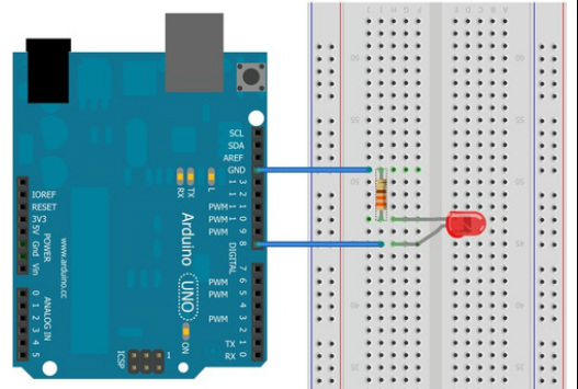
The positive terminal(anode) of the LED is represented by the longer lead of the LED. Since the Arduino is sourcing the current in this case the longer lead should be connected to the pin of the Arduino used in the programming. For our example we shall use the digital pin 8 for this purpose.
The shorter lead will be connected to the ground via the resistor.
Make the connections as shown below:
We will use the digital pins of the Arduino to blink an led.
Components required:
- Arduino (used UNO here has reference)
- A Red LED(for other colours refer datasheet for the current and calculate!)
- A resistor(330 ohms as calculated earlier)
- A breadboard to house the connections.
LED
The positive terminal(anode) of the LED is represented by the longer lead of the LED. Since the Arduino is sourcing the current in this case the longer lead should be connected to the pin of the Arduino used in the programming. For our example we shall use the digital pin 8 for this purpose.
The shorter lead will be connected to the ground via the resistor.
Make the connections as shown below:
Well pretty simple isn't it!?.. More simple than putting it all up here..hehe..anyways! Onto the coding!
Open up the Arduino IDE
In the examples menu you'll see under Basics->blink Led program. Load that up. You'll see the following:
Open up the Arduino IDE
In the examples menu you'll see under Basics->blink Led program. Load that up. You'll see the following:
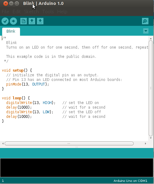
Blink code for the Arduino
Even to the uninitiated,the code is fairly simple to understand. Anyways i'll explain the lines.
void setup()
{
pinMode(13, OUTPUT);
}
This function setup is the initializing function. Thats where you put in the initial setup for the various interfaces you are using. In this example, we are just using one pin to glow the LED on and off and hence we initialize that pin to OUTPUT. That completes the setup function.
void loop() {
digitalWrite(13, HIGH); // set the LED on
delay(1000); // wait for a second
digitalWrite(13, LOW); // set the LED off
delay(1000); // wait for a second
}
he loop function is like the main function, the body of the code. The only difference is that it is like an infinite while loop. Everything inside the loop function is executed infinitely. Again, the body is fairly simple. We are using digital logic (5V -1, 0V -0 ) hence the statement digitalWrite. The syntax is simple : digitalWrite(Pin number,Output_state). When we write it as HIGH, we expect the LED to glow. and when low, the LED will be off.
We introduce a small delay between toggling the LED for reasons obvious to the 'eye' :) . The syntax of delay is delay(time in milliseconds).
Well,pretty simple ain't it!? This program now blinks an LED on and off at the rate of 1Hz on pin number 13.
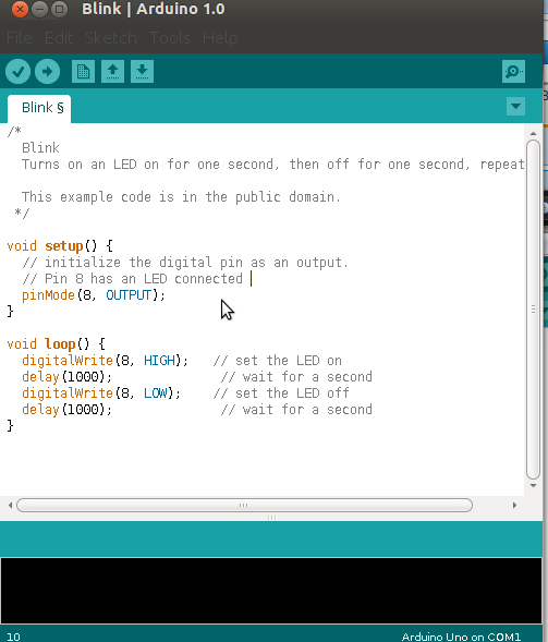
Now we'll need to edit this code slightly to fit our schematics. Remember we have put the LED on pin 8, hence we shall just change two things
1) In the setup function , restate pinMode(13,Output) as pinMode(8,Output).
2)In the loop function , restate digitalWrite(13,HIGH) as digitalWrite(8,HIGH) and digitalWrite(13,LOW) as digitalWrite(8,LOW).
The code will be as follows:
void setup()
{
pinMode(13, OUTPUT);
}
This function setup is the initializing function. Thats where you put in the initial setup for the various interfaces you are using. In this example, we are just using one pin to glow the LED on and off and hence we initialize that pin to OUTPUT. That completes the setup function.
void loop() {
digitalWrite(13, HIGH); // set the LED on
delay(1000); // wait for a second
digitalWrite(13, LOW); // set the LED off
delay(1000); // wait for a second
}
he loop function is like the main function, the body of the code. The only difference is that it is like an infinite while loop. Everything inside the loop function is executed infinitely. Again, the body is fairly simple. We are using digital logic (5V -1, 0V -0 ) hence the statement digitalWrite. The syntax is simple : digitalWrite(Pin number,Output_state). When we write it as HIGH, we expect the LED to glow. and when low, the LED will be off.
We introduce a small delay between toggling the LED for reasons obvious to the 'eye' :) . The syntax of delay is delay(time in milliseconds).
Well,pretty simple ain't it!? This program now blinks an LED on and off at the rate of 1Hz on pin number 13.
Now we'll need to edit this code slightly to fit our schematics. Remember we have put the LED on pin 8, hence we shall just change two things
1) In the setup function , restate pinMode(13,Output) as pinMode(8,Output).
2)In the loop function , restate digitalWrite(13,HIGH) as digitalWrite(8,HIGH) and digitalWrite(13,LOW) as digitalWrite(8,LOW).
The code will be as follows:
And thats it!!! Compile it, upload it and you'll see your LED happily blinking on and off. Isn't it just too easy!? ;)
Food for Thought
Now with obvious questions to the initiated ;)
Q. What happens if I connect the LED between 5V and GND terminal directly?
A. The LED will fuse out. This is because there is nothing to limit the current flowing through the LED except the LED's own small resistance which is in the order of a few ohms. As earlier, i have mentioned that the board can supply upto 500mA, which means this amount of current finds a easier path through the LED and hence fuses it!
Q. Why should the positive lead of the LED be connected to the pin? why not connect the negative of the LED to the pin and the positive to a 5V supply through a resistor?
A. Yes, this can be done too, but you are advised against it!. When an external voltage source is used, we should check upon that source's current driving capability. If you were to use the 5V source provided on board, it can safely source 300mA. Now say you forgot to put the resistance. which means that you have just connected the positive lead of the led to 5V and the negative lead to the pin, then 300mA would flow into the pin destroying the pin(as the pin's max limitation is just 40mA).If careful precautions are taken then connecting this way is fine too.
Q. What if I were to connect the LED in such a way that the positive lead goes into digital pin 8 and negative pin to digital pin 9, and to glow the LED, I set the pin 8 as HIGH and pin 9 as LOW and vice versa to turn it off.
A. An interesting Question!, yes its possible. Notice no resistor has been used, but since the pins are not directly connected to GND or 5V when u program them as 0 or 1 respectively(it consists of a push-pull system), only the required current will flow. Though this is possible, remember that when u turn the LED off you are effectively giving 5V on the negative pin and 0 V on the positive pin. This means that the LED is reverse biased at 5V and it might break down since its break down voltage is around -2V not -5V. Instead of reversing polarity its better to just connect it between pins 8 and 9 and just setting pin 8 as HIGH or LOW that way, the polarities are not reversed, and toggling is also achieved. In this case Pin9 just acts like ground. In this method you'll notice that the pin's brightness cannot be controlled.
Q.How do i control the brightness of the LED?
A. Simple, use a different resistor, or in later tutorials, use PWM(Pulse width Modulation) code.
Feel free to ask any other Q's and I shall add them here for the benefit of everyone. :)
References
For more in-depth detail on LEDs and power systems on Arduino visit -
http://www.ladyada.net/learn/arduino/LEDs.html
