Digital Voltmeter
Now that we have established a communication system to the computer which is programming the device, we make use of this feature to make a small digital voltmeter. This is an indispensable tool in the field of electronics!. Whenever there is a need to debug, we need a voltmeter reading to get a better understanding of the circuit. For this example, we'll use a new tool, Analog Read.So lets get right to it. Onto the theory!
Theory
The theory here will make an attempt to brief ADC(Analog to digital Conversion). Though most programmable pins are 0 and 5V logic(1 and 0) some pins are also 0 to 5V sensitive. These pins are the analog pins. When a certain voltage is given to these pins, within the limits of the reference voltage of course, a digital equivalent can be generated and read into a register inside the Arduino.
The theory for 'sampling' the analog value into a digital value is quite complex, but we will not go into that detail. For, the basic understanding we'll stick to the picture on the left.
Vref is the reference voltage to which the input voltage will be digitized. This means that if Vref is 5V, then the input voltage can vary from 0V(common ground) to 5V.
Arduino has a 10 bit ADC. This means that the analog values can be resolved into a digital value ranging from 0 to 255 where 0 corresponds to 0V and 255 corresponds to 5V.
The working is explained as follows:
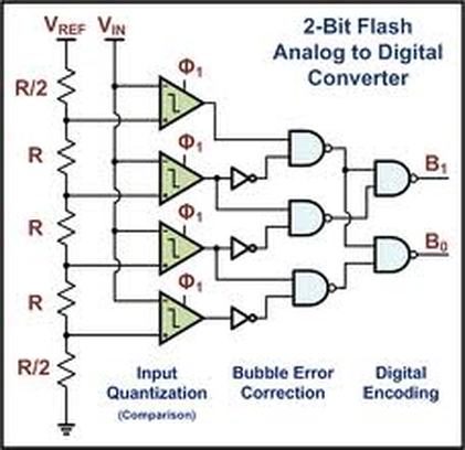
The input voltage is 'quantized' by sampling at constant frequency known as the sampling frequency. This means that every certain amount of time, the value at the analog pin is compared against a set of reference values generated by the main reference voltage.
If vref=5V then, from the circuit on the left, the various reference voltages to the op-amps are 4.375V,3.125V,1.875V,0.625V (got by using resistor divider rule). Therefore, if the Vin(the input voltage) is more than the reference voltage for that op-amp, the output of that op-amp will be high. Lets consider this 2 bit ADC above for a voltage of 2V. 2V<4.375V ,so the first op-amp will send a 5V(logic 1 because its inverting op-amp) as output,similarly its lesser than the second reference(3.125V) hence output is 5V. 2V is>1.875V>0.625V. Therefore the remaining op-amps will give a low output. Now the NAND gates inputs are respectively 1,0 ; 1,1 ; 0,1 ; giving the final output at B as 10 ( 2 in decimal). So, in a 4bit ADC, if the output is 2, the digital reading indicates that the analog value is 3.125V . This quantizing error of 1.25V(max possible error) can be improved by having a higher resolution (i.e higher bit ADC).
The Arduino utilizes a 10bit ADC. This means that 0-5V can be digitized as 0 to 1024 value range. Let's look at the resolution. 5/1024 =5mV . This means that the most possible error in reading is 5mV! thats more than enough for our usage!.
Enough nerding! lets put it in use! :D
The theory for 'sampling' the analog value into a digital value is quite complex, but we will not go into that detail. For, the basic understanding we'll stick to the picture on the left.
Vref is the reference voltage to which the input voltage will be digitized. This means that if Vref is 5V, then the input voltage can vary from 0V(common ground) to 5V.
Arduino has a 10 bit ADC. This means that the analog values can be resolved into a digital value ranging from 0 to 255 where 0 corresponds to 0V and 255 corresponds to 5V.
The working is explained as follows:
The input voltage is 'quantized' by sampling at constant frequency known as the sampling frequency. This means that every certain amount of time, the value at the analog pin is compared against a set of reference values generated by the main reference voltage.
If vref=5V then, from the circuit on the left, the various reference voltages to the op-amps are 4.375V,3.125V,1.875V,0.625V (got by using resistor divider rule). Therefore, if the Vin(the input voltage) is more than the reference voltage for that op-amp, the output of that op-amp will be high. Lets consider this 2 bit ADC above for a voltage of 2V. 2V<4.375V ,so the first op-amp will send a 5V(logic 1 because its inverting op-amp) as output,similarly its lesser than the second reference(3.125V) hence output is 5V. 2V is>1.875V>0.625V. Therefore the remaining op-amps will give a low output. Now the NAND gates inputs are respectively 1,0 ; 1,1 ; 0,1 ; giving the final output at B as 10 ( 2 in decimal). So, in a 4bit ADC, if the output is 2, the digital reading indicates that the analog value is 3.125V . This quantizing error of 1.25V(max possible error) can be improved by having a higher resolution (i.e higher bit ADC).
The Arduino utilizes a 10bit ADC. This means that 0-5V can be digitized as 0 to 1024 value range. Let's look at the resolution. 5/1024 =5mV . This means that the most possible error in reading is 5mV! thats more than enough for our usage!.
Enough nerding! lets put it in use! :D
Practicals:
For this section, we'll use the a potentiometer to generate the different voltages.
Components used:
-Arduino
-Potentiometer
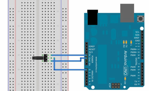
The circuit is yet again simple! We have connected the ends of the potentiometer(pot) to the 5V and 0V(GND), This enables the middle pin of the potentiometer to give readings from 0V to 5V as we turn the knob. This will be displayed on the serial monitor of the computer as an equivalent voltage level. If you have not worked with serial communication, refer to Communication.
The centre pin of the pot which will be used as our input voltage has been connected to pin A0 (The pins A0 to A5 suggest analog pins and can be used as digital pins also if required)
The code for this is as follows:
Components used:
-Arduino
-Potentiometer
The circuit is yet again simple! We have connected the ends of the potentiometer(pot) to the 5V and 0V(GND), This enables the middle pin of the potentiometer to give readings from 0V to 5V as we turn the knob. This will be displayed on the serial monitor of the computer as an equivalent voltage level. If you have not worked with serial communication, refer to Communication.
The centre pin of the pot which will be used as our input voltage has been connected to pin A0 (The pins A0 to A5 suggest analog pins and can be used as digital pins also if required)
The code for this is as follows:
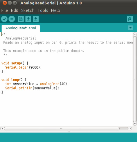
The code is very simple. Just a one line add-on to the previous serial code.
In the Loop function, we wish to continuously sample the pin A0 by calling the
analogRead function. This returns a value of 0 to 1024 into the int variable sensorValue.
I leave it to the users to convert this value to a voltage reading.
Hint: in Serial.println , just add a multiplication factor to sensorValue to convert 0 to 1024 to 0 to 5V.
compile and run the code, and in the serial monitor on the computer you should be able to see the voltage value print infinitely amd also change as you rotate the pot.
So simple! :D
Food for Thought:
Q.You mentioned that the ADC uses sampling time? Should we take into consideration of the time elapsed?
A. Depends on the application, but most situations does not require it. Do notice that each ADC can only be sampled individually and not together in one shot. So,if you were to sample all analog pins, then time considerations might show up, but even then, its manageable.
Q.Is there a way to change the range of values to an upper limit and lower limit instead of 0 to 1024?
A. yes, It is possible. The function is called map. You can use it like this : int OutputValue=map(sensorValue , 0 , 1023 , 0 , 255) in the above code. This returns a value to the 'OutputValue' ranging from 0 to 255. So we have effectively scaled a 10bit to 8bit resolution. This is helpful when data has to be transmitted byte wise in serial communication.
Q.Can analog pins be used as PWM output pins?
A. No,they are strictly read only for analog. But, they can also be used as DigitalWrite or DigitalRead . The parameter to those functions will still be A0-A5.
Q.How do i sample a voltage that is not supplied from the Arduino board(external sensor, etc)?
A.you need to have a common ground between the two devices. Say your external sensor is connected to A0, then make sure that the ground pin of the external sensor is also connected to AGND on the Arduino, which is the in the case of the board ANY GND pin. This way the Arduino knows that the 0V reference of the sensor to calibrate the reading.
Q.How do i sample voltage of different reference(instead of 0-5V , need to use 0-3V)?
A.For this, you need to generate the reference voltage and pass it to AREF pin on the Arduino, I wouldn't recommend this as it unnecessarily wastes power. Instead use the existing readings and use constrain(click to see usage) to saturate values above 3V. Also note that the AREF voltage cannot be greater than 5.5V.
