Fading LED (Analog Write)
In the Last tutorial, we have successfully managed to interface a button to toggle a LED. This time we'll learn to control the brightness of the LED. We will use something called as AnalogWrite to accomplish this. Ever seen those fading lights on a lot of phones that give a 'breathing' effect? Glowing up and dimming down continously? We are going to do just that now! On with the theory!
Theory

Until now we were using digitalWrite function which is very simple to understand. HIGH referred to 5V or LOGIC 1 and LOW referred to 0V or LOGIC 0. Now we are going to use analogWrite which defines levels between these two voltages and assigns a digital integer number to them. We will try to define a 8 bit DAC(Digital to Analog Converter). To put simply, it just converts a 8 bit value (0 to 255) to voltages ( 0 to 5V). This means we can now access voltage outputs of steps =5/255=0.02V.
We shall touch upon a simple idea of PWM here to get a simple understanding of how this works. Imagine a voltage wave which is on for 0.5 sec and off for 0.5 sec and so on(refer to 50% duty cycle in figure). This means that it alternates between 5V and 0V every one second..if you were to average it out for one second then the average value would be (5+0)/2 = 2.5V . This is the effective DC voltage coming at the output pin.
Now if it was on for a shorter time and off for a longer time(20% duty cycle example), then output = 0.2*5=1.0V.
The effect of these changing voltages will show on the LED as a dimmer source or a brighter source. So effectively all we are doing is to split the 100% into 255 digital levels so that we can have varying voltages of step resolution=0.02V.
So the crux of the theory is this. Suppose we write a value of 128 to analogWrite, its equivalent to a 50 duty cycle of a square wave appearing at the output. Since the LED is a DC device, it will recognise the average value of this wave which is 50% of 5V =2.5V and hence will glow half as bright as it would have for a digital value of 255 =>100% duty cycle => constant 5V.
Now onto the practical section.
Practicals

This is exactly like the first LED blink program we wrote. The only difference being that the LED is now connected to pin 9 instead of 8. This is something we have to pay careful attention to. The Arduino has only 3 Hardware PWM channels capable of analogWrite( Pins 3,6,9).
The rest are digitalWrite only!.
Nothing more to explain! onto the code!
Go ahead open the code from examples->Basic->Fade.
The rest are digitalWrite only!.
Nothing more to explain! onto the code!
Go ahead open the code from examples->Basic->Fade.
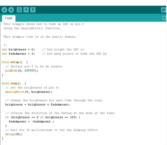
Yet another easy code!
Setup function initiates pin 9 as an output pin.
In the loop function, we call the function analogWrite to output a 8 bit value to the pin 9. Starting from 0. It is then incremented by a value =fadeAmount preset as 5.
therefore in the successive iterations the value output is 5,10,15,20,etc till 255 once we reach 255 there is an if condition that says fadeamount will now be =-5 which will count down from 255 to 0 and again up to 255 and so on..
once the value is written to the output pin we delay for 30ms . This is purely for the eye to be able to distinguish it rising and dimming.
Pretty simple huh!?
Compile it off and run it to see the magic. I think you can put this code into a night lamp and give a nice effect..of course u'll need to do the circuit for a lamp not for an LED .. :D
Food for Thought
There always is a Question :D
Q. Dosen't the resistor value make a difference for every changing value of the voltage at the pin?
A. No, it does not. The resistor is just a current limiting component. What we need is a changing brightness with respect to the voltage we give. In fact putting a resistor value of 100 ohm when the analog value is approx 70 would give the same brightness as that of 5V and 330 ohm.
Q. What other applications?
A. Quite some actually.. how about a buzzer which can act like a siren. You could also use this to do speed control of motors(future tutorials will show how).
Q.Can this be used as a variable power source from 0V to 5V?
A. Definitely NOT!. Its just a signal not a power source..A power source requires substantial amount of current to support the components its connected to. This cannot act as such a source. But it can trigger a voltage controlled source or a current controlled source.
