Introduction
Many projects require power supplies of various voltage and current ratings. The components/ICs used may require different voltages to run. Sometimes different voltages at different times!. A plan is required to provide the right voltage and current to the components. For this purpose, we shall look into a few concepts mainly , voltage regulators - constant voltage source,current regulators - constant current source and voltage dividers.
Voltage Regulators
Most of the ICs require a VCC(power source) of 5V or 3.3V. A typical battery eliminator available in the market is 12V. how do we step it down to 5V or 3V? . Answer: By using a voltage regulator.
A voltage regulator is a device/IC which takes in a higher voltage and steps it down to a lower voltage (DC-DC). For the purposes of robotics and other open source projects on this site, we will look into simple voltage regulators like the 78xx series.
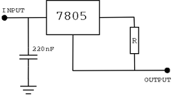
7805 - This is a 5V regulator. It can take in an input of almost upto 35V (refer datasheet) and give a constant output of 5V. This does not mean that we give a 35V to the input and expect it to power all 5V devices!. As pointed out in the previous post, current is the important factor that determines the performance. usually the 78xx series can source a maximum of 1A. Again, this does not mean that we can give a 35V 1A as input and expect a constant 5V 1A output. What else are we missing? , its the power rating!. 5V 1A generates around 5W of power. if we give a 35V 1A input, then we are generating around 35W of power !. This can heat the device to such an extent that it damages the device!. Therefore, the optimum range of voltage input can be around 7V to 12V to the 7805 for example.
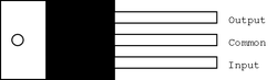
Connecting the regulator IC is very simple, as shown below. Pin 1 is the input (higher voltage). Pin 2 is the common GND. Pin 3 is the output(constant voltage).
The capacitors are to filter out any spikes in the current or voltage that might occur by using devices like high power motors.
A voltage regulator is a device/IC which takes in a higher voltage and steps it down to a lower voltage (DC-DC). For the purposes of robotics and other open source projects on this site, we will look into simple voltage regulators like the 78xx series.
7805 - This is a 5V regulator. It can take in an input of almost upto 35V (refer datasheet) and give a constant output of 5V. This does not mean that we give a 35V to the input and expect it to power all 5V devices!. As pointed out in the previous post, current is the important factor that determines the performance. usually the 78xx series can source a maximum of 1A. Again, this does not mean that we can give a 35V 1A as input and expect a constant 5V 1A output. What else are we missing? , its the power rating!. 5V 1A generates around 5W of power. if we give a 35V 1A input, then we are generating around 35W of power !. This can heat the device to such an extent that it damages the device!. Therefore, the optimum range of voltage input can be around 7V to 12V to the 7805 for example.
Connecting the regulator IC is very simple, as shown below. Pin 1 is the input (higher voltage). Pin 2 is the common GND. Pin 3 is the output(constant voltage).
The capacitors are to filter out any spikes in the current or voltage that might occur by using devices like high power motors.
Current Regulators
There are some rare cases where a constant current source is required. For the sake of simplicity we shall discuss a small variant of the voltage regulator itself to generate a constant current source.
The figure shown here demonstrates a simple current source where the R value can be tuned to give the right current. @5V and 10ohms, the current got is 500mA (using Ohm's Law) . Be careful to notice that the current flowing through the resistor generates around 2.5W! therefore choose the right resistor. We shall not dwell deeper into this topic as it is not required for most of the ideas discussed here.
The figure shown here demonstrates a simple current source where the R value can be tuned to give the right current. @5V and 10ohms, the current got is 500mA (using Ohm's Law) . Be careful to notice that the current flowing through the resistor generates around 2.5W! therefore choose the right resistor. We shall not dwell deeper into this topic as it is not required for most of the ideas discussed here.
Voltage dividers
Sometimes, we require to generate voltage references (in the case of op-amps etc). such applications does not require a voltage regulator as there is very minimum current transferred. It is enough for the application to just sense the voltage. In such situations we make use of a very simple idea of voltage dividers. Keep in mind that the application of such dividers are mainly to generate voltage reference and NOT to source the current at that voltage.
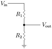
A typical voltage divider consists of resistance bridges and a voltage source. Let us try to generate a 3V voltage reference from a 5V voltage source.
Consider the circuit diagram as shown. A 5V source is sourcing current through a set of two resistors in series. It is desired to generate a 3V reference at the interface of the two resistors. A simple formula for this would be R2/(R1+R2) * 5V = 3V .. Let us choose R1=1k ohm. The formula gives R2 to be 1.5k Ohms. Putting these resistance in the circuit will give us the required voltage reference of 3V at the output.
But this is easier said than done. 1.5k Ohms is not a standard resistance available in the market. Therefore the work around for this problem is to use a potentiometer. A potentiometer is a device which can give a range of resistances. It can be tuned to give a fairly accurate resistance. we shall see how
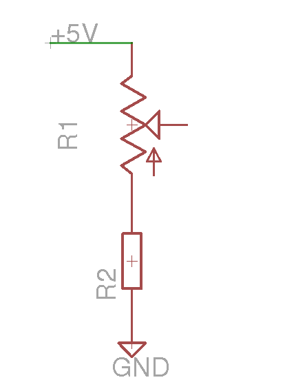
with pot
When we use a potentiometer we can tune it to the required resistance value. Therefore we shall modify the circuit slightly as shown above. Now as we tune the potentiometer, we get different voltages. The range of voltages that we can get can be calculated as follows. Let us consider a 10k ohm potentiometer. This means that across the ends of such a potentiometer 10k Ohms of resistance is constant. The value that varies is at the centre pin. Therefore we can have a range of 0 to 10k Ohms at the centre pin. This means that if the centre pin reads 0 ohms, the output voltage calculated as R1=0 with R2 still =10k ohms gives 5v and with R1=10k ohms with R2 constantly at 10k ohms gives output as 2.5V. by turning the potentiometer, we can therefore get the values of 2.5V to 5V.
